SPICE Simulation Analog and Mixed-Signal Circuit Design Tools Magnetics Transformer Design and Test Program Development. Eddy-current loss is a function of the frequency of the power source and the thickness of the core-steel laminations.
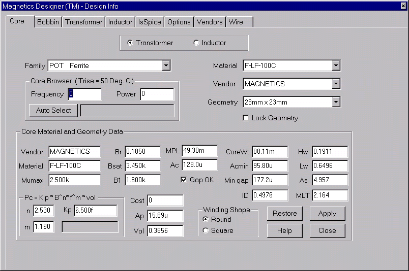
Magnetics Designer Transformer And Inductor Design And Analysis Made Easy
Dixon Transformer and Inductor Design for Optimum Circuit Performance UnitrodeTI Design Seminar 2002 TI slup205pdf are presuming an ungapped.

. PowerEsim is free SMPS power supply design manufacturer product databaselist switching converter topologies circuit analysis magnetic design software transformerinductor simulation calculation software DVT Differential mode EMI simulation EMI measurement Harmonics Thermal MTBF Life time and Monte Carlo analysis tool. The transformer inrush current is also plotted as a single point on the TCC diagram. The circuit connection shall be made as shown Figure 4The primary current of minimum of 25 rated primary current to be injected on primary side of CT with secondaries shorted and the secondary current can be measured and recorded for all cores.
Inrush currents tend to be asymmetrical when viewed on an oscilloscope. There are four typical types of current transformers. The above mentioned IEEE transformer test code recommends the average-voltage voltmeter method to be described below for measuring no-load loss.
I was assuming that the magnetizing current wont fall to zero which would relate to a relative large flux in ungapped core. These differences in the unbalanced and 100 damage curves can. Current Transformer Types.
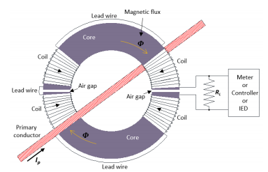
CT secondary circuit must be grounded and grounded at one point onlyIf the secondary of CT is left unloaded a risk of explosion exists. Window bushing bar and woundThe primary winding can consist merely of the primary current conductor passing once through an aperture in the current transformer core window- or bar-type or it may consist of two or more turns wound on the core together with the secondary. A clever solution to the problem of false 87 relay tripping due to transformer inrush current is called harmonic restraint or harmonic blocking.
You may also read. Eddy loss is strongly influenced by harmonics in the impressed voltage. Magnitude of the induced EMF or Voltage in a transformer can be found by EMF equation of the transformerWhen a source of alternating current AC is applied to the primary winding of the transformer which is known as magnetizing current it produces alternating flux in the core of a transformer.
With Build 4545 release all new users and those on current maintenance will also receive our CMSDK. The produced alternating flux in the primary of the. It support LED driver design PFC.
Figure 4 Current transformer in MV switchgear. Any differential current relay will naturally see this difference as a fault and may trip power to the transformer unnecessarily. The following enhancements have been added to the software running on Windows.
Again as part of the initial design the transformer inrush current must be to the left of the transformer primary fuse curve otherwise the fuse will open when the transformer is energized. Transformers Fire Protection System Causes Types Requirements Special precautions must be taken when connecting CT primary connection points are usually. I see however that basic forward converter design instructions eg.
Intusofts Home Page. Turns ratio Tests optional test This test is to ensure the turns ratio of CT at all taps.
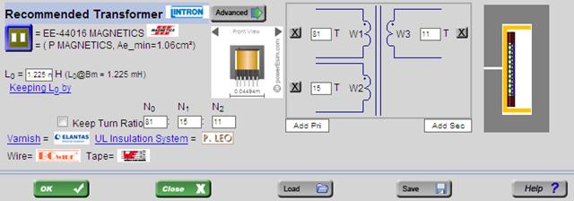
Magnetics Builder Magnetic Design Software Design Magnetic Inductor And Transformer Tool

Software Solutions
Ht Lt Current Transformer Design Software Ht Lt Ct Design Software Tool Low Tension Ct Design High Tension Ct Design Softbitonline New Delhi India
![]()
Current Transformer Ct Saturation Calculator Eep
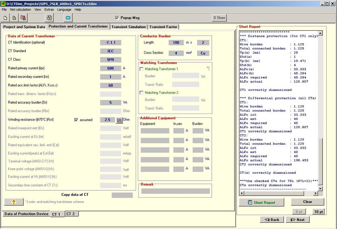
Ctdim Current And Voltage Transformer Selection Dimensioning And Simulation Protection And Control Siemens Global
Current Transformers How To Project Altium Designer Projects
Magnetics Designer Transformer And Inductor Design And Analysis Made Easy
Electromagnetic Simulation Of Split Core Current Transformer For Medium Voltage Applications
0 comments
Post a Comment